Explore our innovative software packages
Explore our innovative suite of software and services, trusted by a wide range of international organisations and industries. We help bring cutting-edge design concepts to life, providing effective solutions. Organisations choose BEASY as their simulation partner to address intricate engineering challenges and support life extension programs.
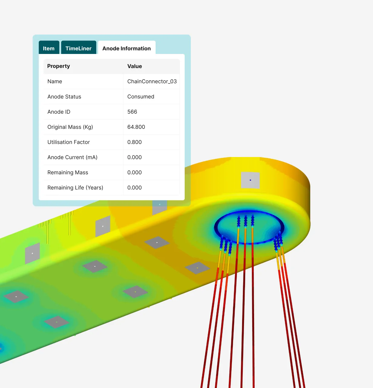
CP Digital Twin
BEASY CP Digital Twin provides corrosion and cathodic protection engineers with the data needed to make fast and informed decisions and provides actionable simulation insights into operations. With a digital twin, engineers can determine the ideal design before the asset goes into operation. Integrity engineers can react to anomalies based on the predicted health management information and deep insights gained from the digital twin.
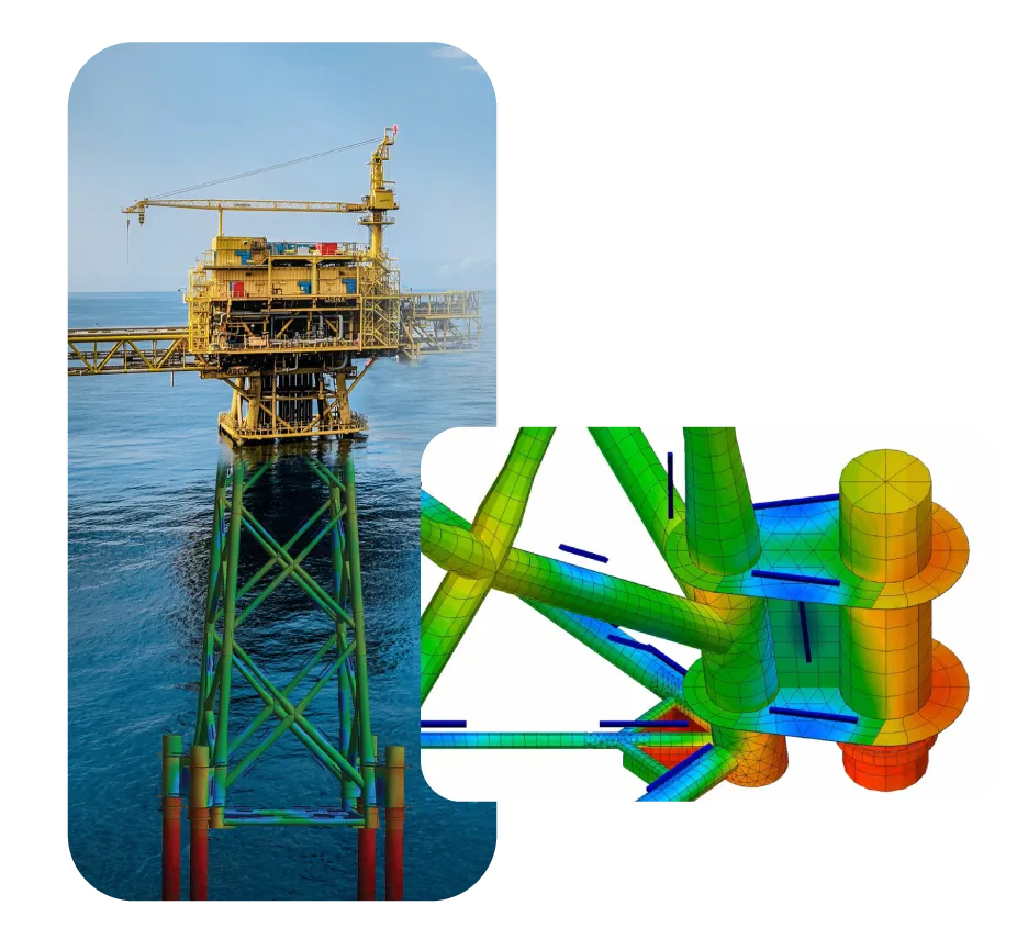
Corrosion & CP
BEASY Corrosion and Cathodic Protection (CP) is a cutting-edge solution meticulously crafted to replicate the intricacies of galvanic corrosion challenges and cathodic protection strategies. Unlock the power of BEASY CP to delve into corrosion analysis and monitor the effectiveness of a chosen cathodic protection system. Suitable for both offshore and onshore fully immersed electrolyte environments.
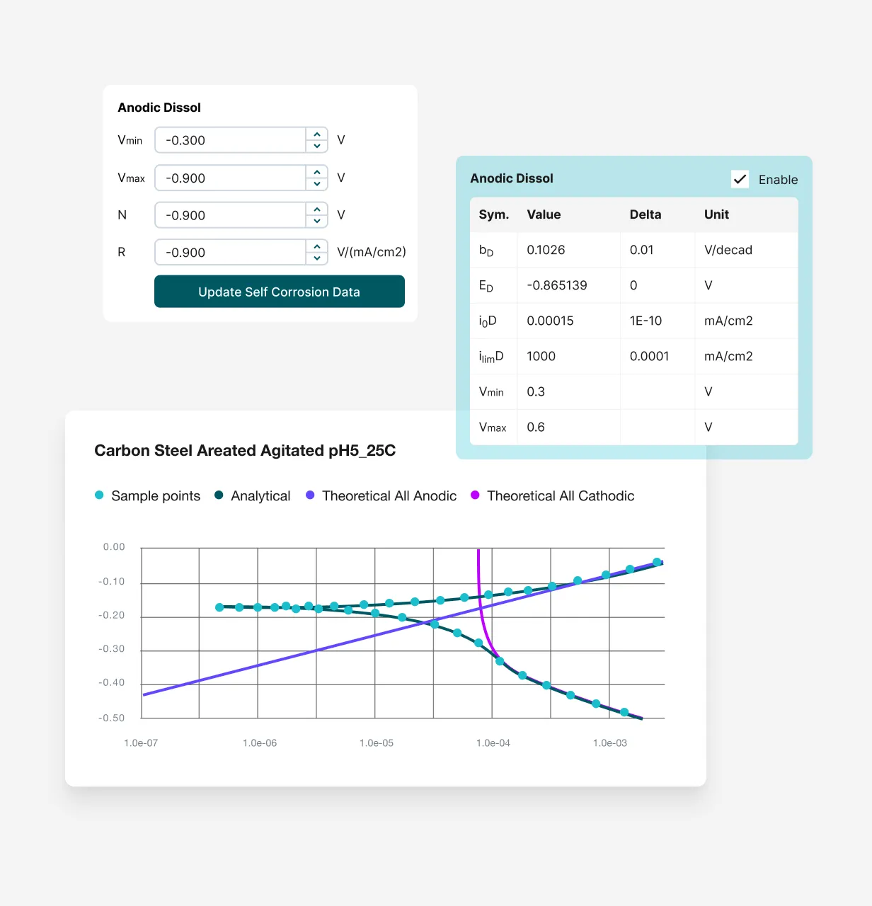
PolCurveX
PolCurveX is the ultimate polarisation data management solution. Unveil the intricacies of material behaviour using deconvolution for better support of recent MIL-STD-889-D standards. With PolCurveX, effortlessly import, export, store, and manipulate polarisation data across a diverse range of formats. Seamlessly interact with this essential tool that perfectly complements BEASY Corrosion Manager.
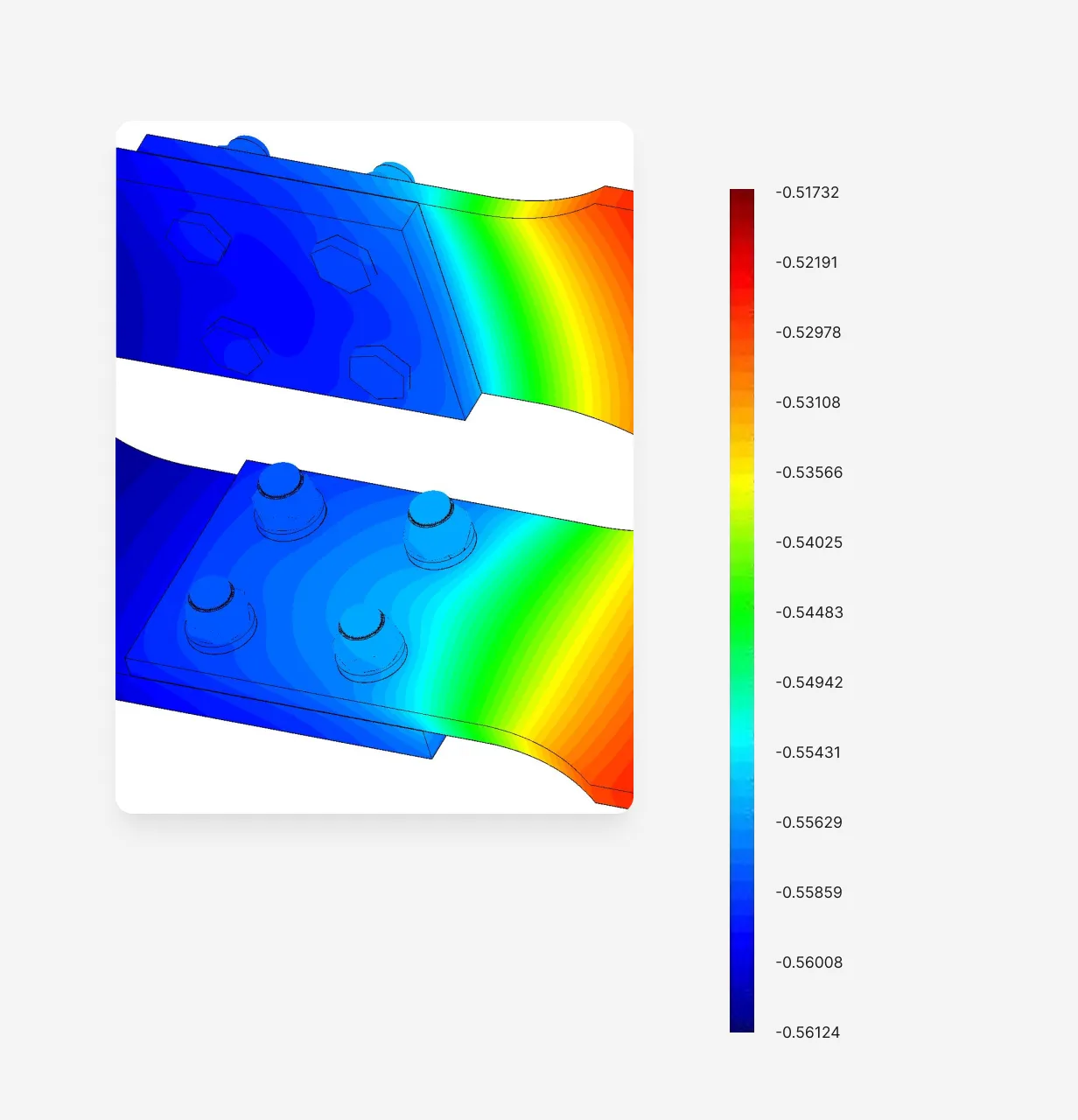
Corrosion Manager
BEASY Corrosion Manager is the ultimate tool for foreseeing corrosion rates, corrosion currents, and polarisation potentials within three-dimensional galvanic corrosion models. Tailored for structures immersed in either bulk or thin electrolyte environments, this exceptional solution is particularly adept at addressing atmospheric corrosion scenarios. Confidently anticipate corrosion rates with BEASY Corrosion Manager.
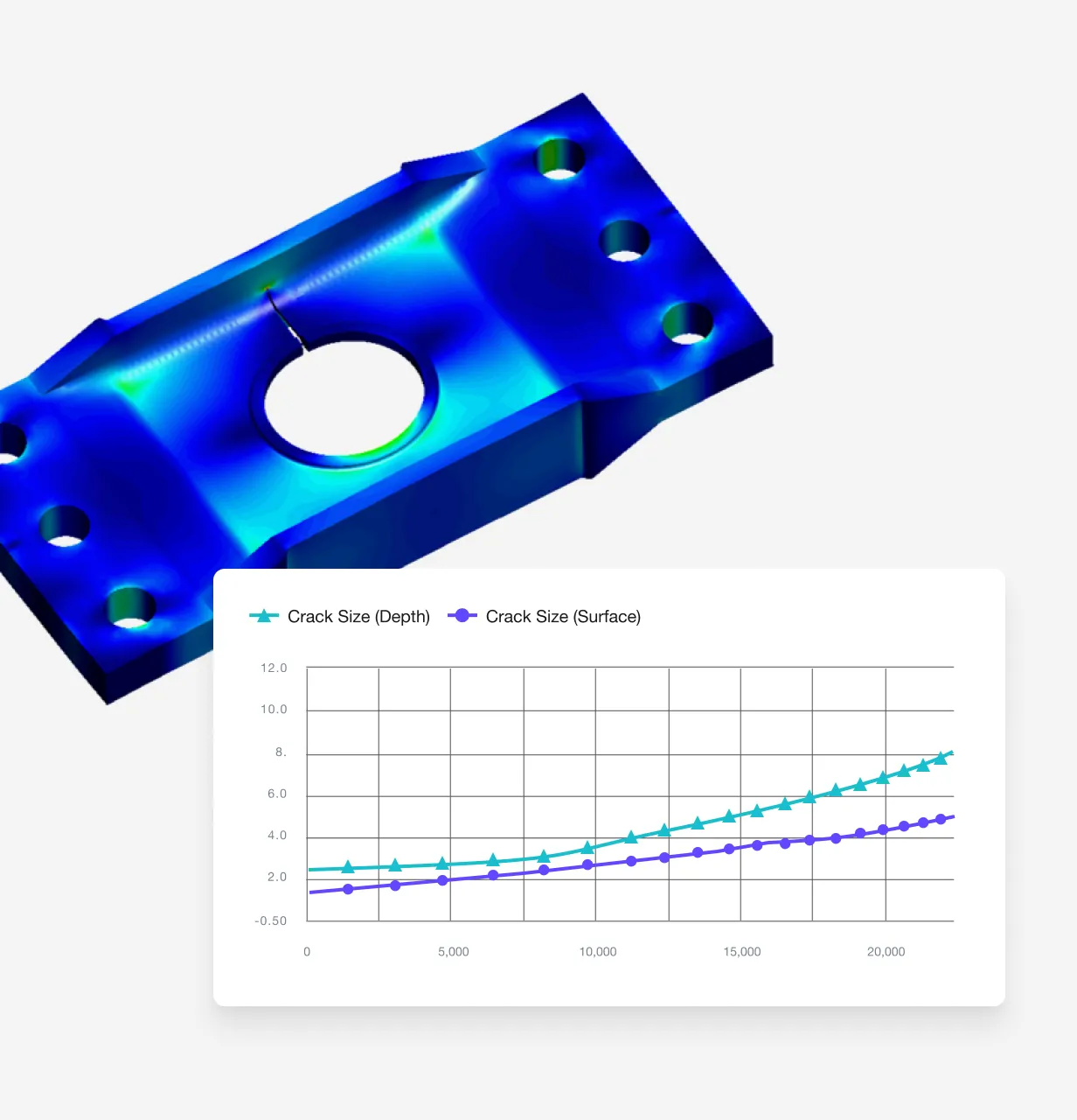
Fracture & Crack Growth
BEASY Fracture & Fatigue Crack Growth (FCG) is a breakthrough solution for engineers seeking precise fracture mechanics models for structural components. This innovative technology allows for damage-tolerant design assessment with accurate stress intensity factor (SIF) solutions and three-dimensional crack growth simulations, gaining vital insights into crack growth rates and shape evolution.
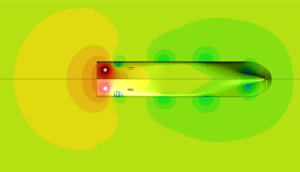
UEP & CRM Signatures
BEASY’s Signature Management solutions provide a comprehensive solution for engineer swishing to predict and manage corrosion related electric and magnetic fields. Corrosion related electric (UEP) and magnetic fields (CRM) have an important role in the design of naval vessels and their associated signatures.
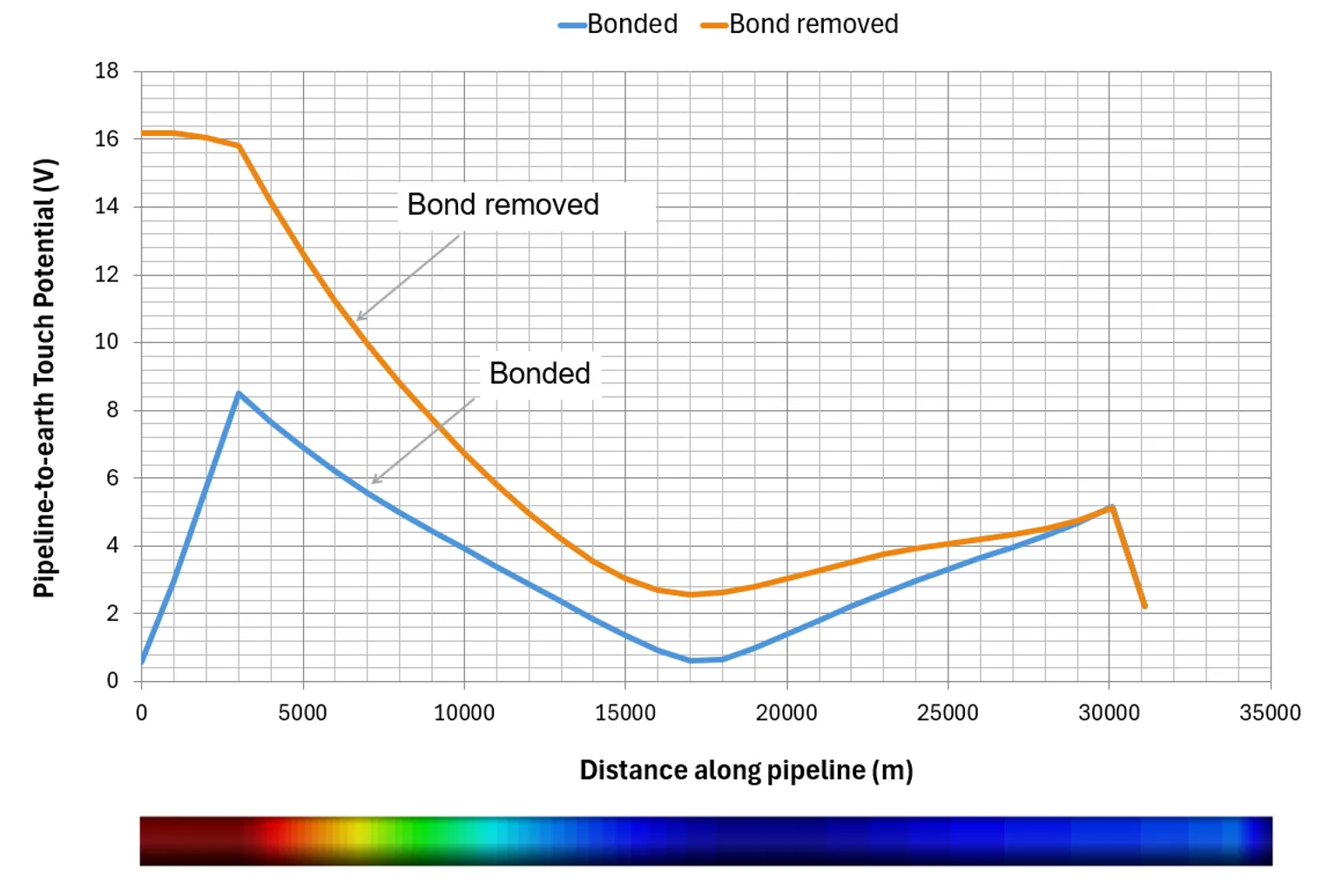
AC Interference
An advanced tool for pre-emptively estimating induced voltages within pipelines situated beneath low-frequency overhead power lines, AC Interference can calculate potentials induced along pipelines as a result of alternating current (AC) flowing through high-voltage overhead powerlines in close proximity. Produce fast results and anticipate anomalous potential disruptions along a pipeline.
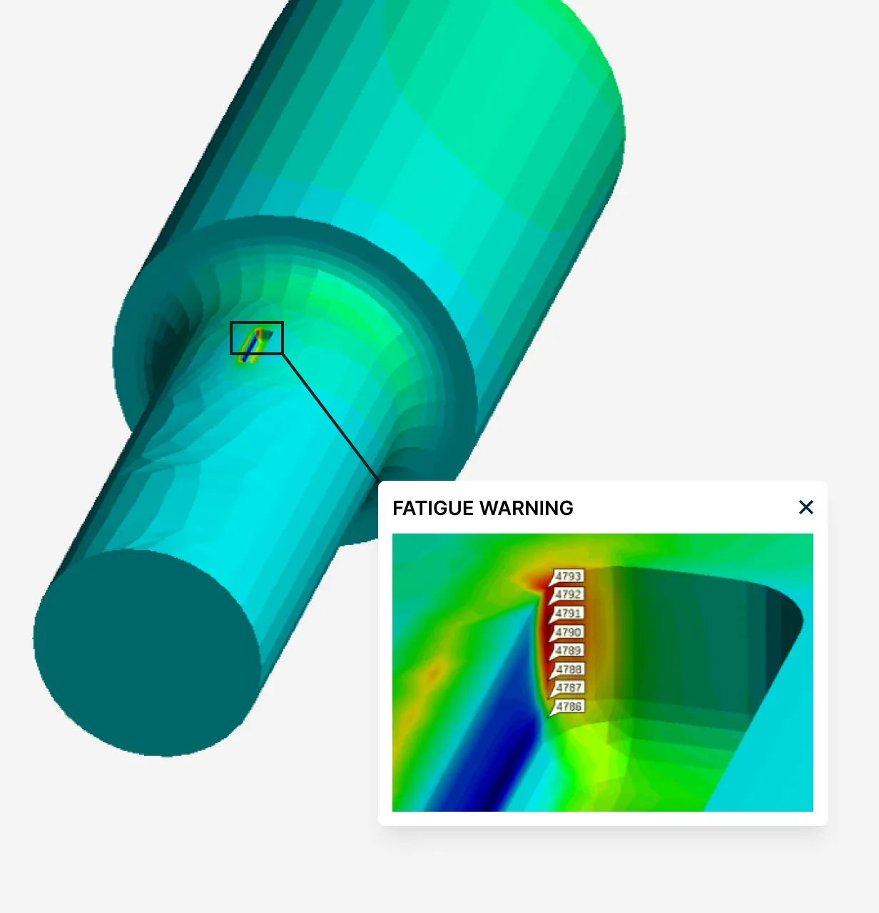
FASST
Revolutionise stress analysis models by scanning simulation models to pinpoint potential areas of crack growth. With BEASY Defect Scanner, engineers can scan stress models and easily gain insights into estimating critical crack sizes within areas of structures and components. These simulation models provide an enhanced understanding of structural integrity and allow for predictive maintenance.
Add-On Software
Along with BEASY’s extensive range of stand-alone software, we offer a variety of add-ons to assist engineers and systems designers with their workflow and processing. This also allows models created in third-party software to benefit from BEASY’s powerful simulation and time-stepping capabilities.
Industry Leading Detection & Prevention For You
BEASY's software products and services help organisations solve complex engineering challenges.