
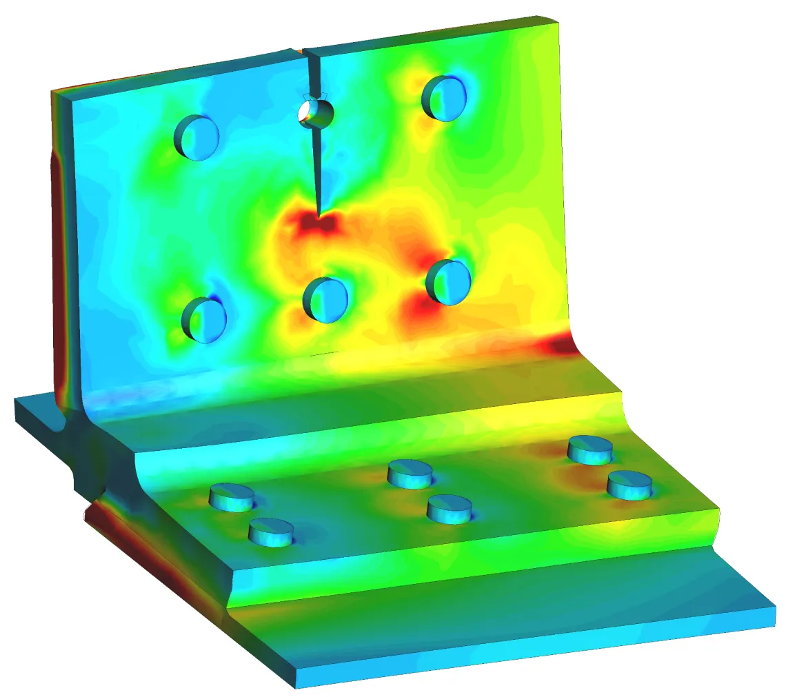
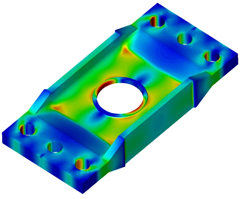
Fracture & Crack Growth
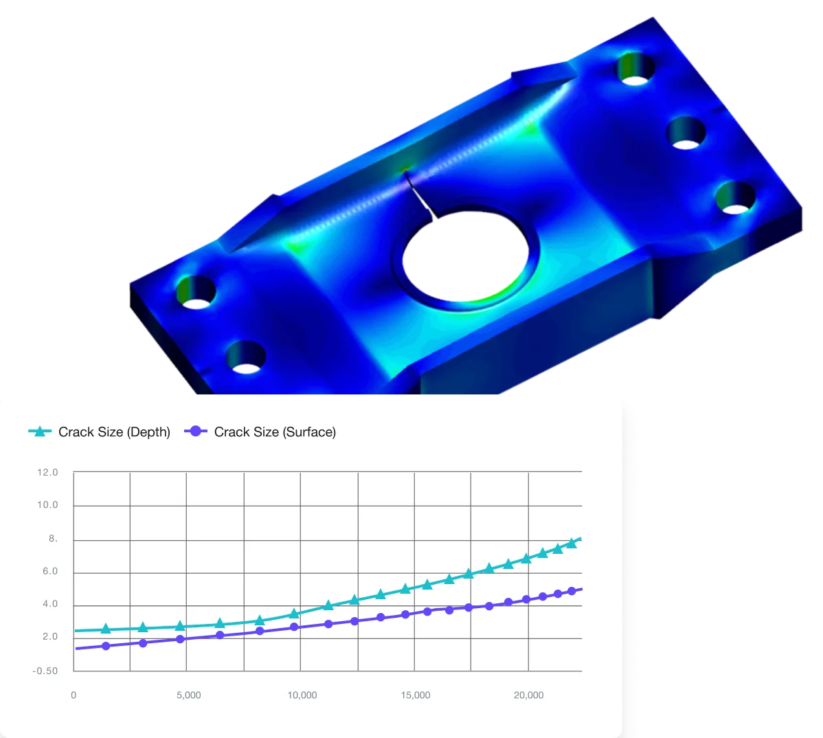
BEASY’s Fracture & Crack Growth (FCG) software enables engineers to quickly develop high fidelity fracture mechanics models based on the actual structural component. This software is used by engineers, performing damage-tolerant design assessments, to determine accurate stress intensity factor (SIF) solutions and simulate 3D crack growth. The BEASY SIF Wizard provides an interactive GUI that engineers can use to automatically insert, parametrically controllable crack shapes, in models. Our easy-to-use modelling process supports the setup and launch of a FCG simulation using the BEASY Crack Growth Wizard - providing critical data on crack growth rates and crack shape evolution.
Typical Applications


Benefits
Fracture Mechanics Solver
BEASY utilizes a multi-threaded, dual boundary integral solver, with parallel processing capability to solve computational fracture mechanics problems. This technology more accurately represents the near singular stress fields that occur near the crack front. BEASY’s surface only meshing is very efficient for crack modelling and integrates well, with automatic meshing routines used to advance cracks in structural models. The software can also use more globally oriented FE solutions as input to fracture sub models when needed.
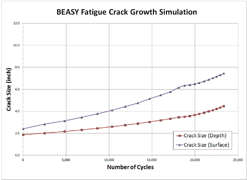
BEASY supports both 2D and 3D crack growth simulations. Crack growth directions and rate are computed at discrete locations along the crack front. Crack grow direction is predicted using computed SIF values. Load spectrum data can be generated using a number of supported industry formats including block spectrum, sequential, multi-axial, and others.
A variety of crack growth relationships (Paris, NASGRO, AFRGROW, etc) are also available to compute da/dN rates or test data can be supplied in a tabulated da/dN format. In addition for stress corrosion crack growth, a sustained crack growth rate da/dT can be used.
Elevate your expertise
BEASY offers a variety of training options: from comprehensive full courses, to webinars and tailored training program, our experts in corrosion and fracture ensure that you get the most out of BEASY's software.